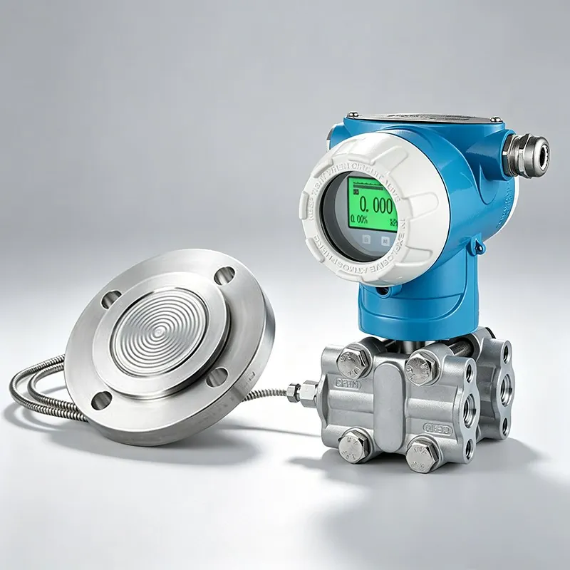
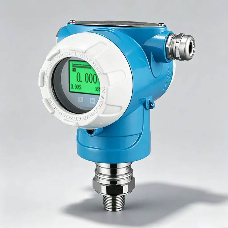
An edge project starts with a verified measurement loop, not with a dashboard. A pressure, level, temperature or flow instrument first has to produce a signal that is appropriate for the process and the selected order code. The edge layer can then acquire, timestamp, normalize and forward that signal. A visually similar transmitter must not be assumed to support HART, RS485, Ethernet or wireless communication unless the selected configuration and its technical document say so.
Define the measurement source
| Input to confirm | Why it matters |
|---|---|
| Measured variable and engineering range | Determines scaling, alarm interpretation and historian units. |
| Signal and protocol | 4–20 mA, pulse, frequency or a documented digital interface require different input hardware. |
| Power and isolation | Loop loading, grounding and isolation affect reliable acquisition. |
| Update rate and timestamp | The process time constant and decision use determine a sensible sampling interval. |
| Quality/status information | Out-of-range, maintenance and communication states should not be stored as normal process values. |
Integration sequence
- Verify the field measurement locally and record its normal, minimum and maximum values.
- Confirm the exact electrical interface and wiring against the selected TYCK document.
- Scale the gateway channel with units and tag identity; keep the raw value available for diagnosis.
- Test loss of power, open circuit, over-range and communication interruption.
- Send only the data needed by the control, maintenance or analytics use case.
- Document firmware, mapping and change control before production use.
Limits and terminology
A software model becomes useful only when the field tag, configuration and operating context remain traceable. Calling a visualization a “digital twin” does not improve the underlying measurement. Likewise, an edge gateway does not add an unlisted sensor accuracy or approval. Cybersecurity, network ownership, retention and remote-access rules must be handled by the plant’s responsible teams.
Selection input: provide the instrument model/SKU, output, power, range, units, required sampling interval, existing PLC/DCS interface, network boundary and the intended decision. TYCK can then confirm which information belongs to the instrument and which must be implemented by the integration system.