TYCK Product Matrix

Industrial Temperature Instruments

Compare TYCK industrial temperature instruments for temperature sensors, head transmitters and smart transmitters. Review selection factors, applications, limitations, published products and request a configuration-specific quote.

2 Product results

Engineering Selection Guide

Category overview

An industrial temperature point is an assembly: sensing element, sheath, insulation, thermowell or direct-insertion construction, process connection, extension, terminal head and sometimes a transmitter. Performance cannot be assigned to the head alone. Begin with the real minimum, normal and maximum process temperatures, the permitted response time and the process medium. Then determine whether the sensor can contact the medium directly or needs a pressure-retaining thermowell that permits removal while the process remains closed.

RTDs and thermocouples have different signal levels, wiring and application behaviour. An RTD circuit must account for lead resistance and wiring arrangement; a thermocouple circuit needs the correct thermocouple and extension-wire types plus cold-junction handling. Cable insulation, sheath material and junction construction must tolerate both process and ambient conditions. Electrical noise, ground loops and long cable runs may favour conversion to a robust current signal near the sensor, but the chosen transmitter input and isolation have to match the assembly.

Mechanical design often controls reliability. A thermowell in flowing service experiences bending and cyclic loading, so insertion length, diameter, material, wake effects and process velocity require engineering review. Excessive mass can slow response, while insufficient insertion may introduce conduction error from the vessel wall or pipe. Vibration, thermal cycling, washdown, sanitary cleaning and accessibility affect head style and mounting. These details are specific to the installation and should be captured on a drawing rather than inferred from a generic probe photograph.

For a TYCK enquiry, state sensor type, element count, class or tolerance requirement, measuring range, sheath or thermowell details, insertion and extension lengths, process connection, head and cable entry, transmitter signal and required documents. Product families below show available directions, but exact range, tolerance, pressure boundary, material and hazardous-area status belong to the selected SKU. Request the matching datasheet and drawing before finalising the process connection or control-system scaling.

Selection factors

Sensor and circuit
Specify RTD or thermocouple type, number of elements, two-, three- or four-wire RTD connection, thermocouple junction arrangement, required tolerance and the transmitter or input card that will receive the signal.
Mechanical assembly
Define direct insertion or thermowell, sheath and well materials, insertion and extension lengths, process connection, tip construction, mounting orientation and whether the sensor must be removable without opening the process.
Thermal and dynamic duty
Give normal and extreme temperatures, pressure, flow velocity, vibration, cycling rate, required response and ambient heat around the head. Flowing thermowells may need a documented mechanical calculation by the responsible party.
Installation evidence
List cable entry, enclosure, washdown, hazardous-area need, drawings, material records and calibration requirements. Confirm the exact sensor-transmitter combination and configured input range on the order record.

Typical applications

  • Pipe and vessel measurements where insertion depth, wall conduction and response time are reviewed as part of the installation.
  • Steam and utility services where thermowell strength, process connection and access for sensor replacement are important.
  • Package equipment and control panels that convert an RTD or thermocouple signal to a standard loop or digital interface.

Limitations and confirmation points

  • A probe's usable temperature is limited by its weakest configured component, including element, insulation, sheath, seal, head, cable and transmitter; a family-level temperature claim is insufficient.
  • Do not choose a thermowell solely by thread and insertion length. Pressure, velocity, material, geometry and cyclic loading require project-specific mechanical review where applicable.

Product Catalog

Temperature

2products

Compare Selected 0/4

Select at least two products to compare.

Temperature Transmitter

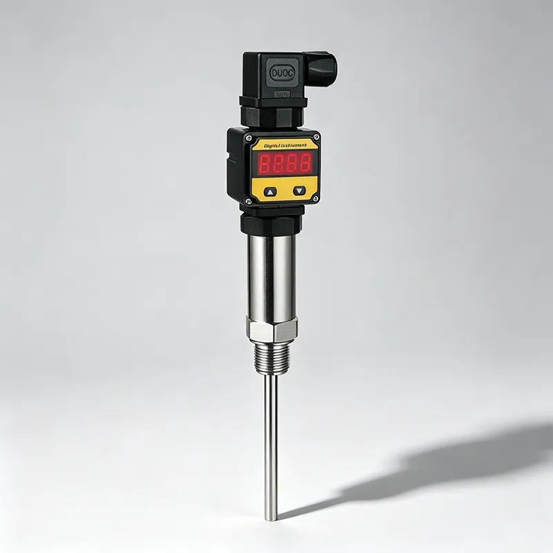
TYCK THERMO T210 Head-Mount Temperature Transmitter

Head-Mount Temperature Transmitter with configuration-specific range, connection, material and output options

  • Platform modelT210
  • Product typeTemperature transmitter

Process skids requiring a standardized RTD or thermocouple signal interface.

Documents Request quote
5 SKUs

Temperature Transmitter

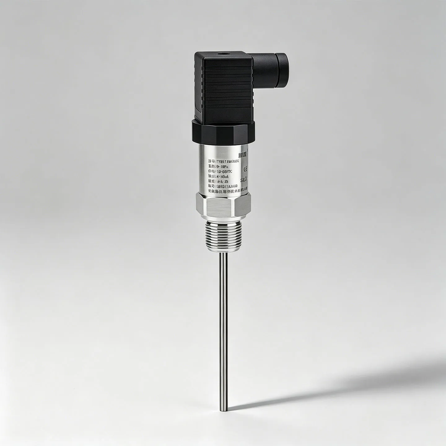
TYCK THERMO T310 Smart Temperature Transmitter

Smart Temperature Transmitter with configuration-specific range, connection, material and output options

  • Platform modelT310
  • Product typeIntelligent temperature transmitter

Process skids requiring a standardized RTD or thermocouple signal interface.

Documents Request quote
25 SKUs

Engineering Selection Guide

Frequently asked questions

Should an RTD or thermocouple be selected first?

Start from the process temperature range, required tolerance and response, mechanical environment, cable distance and receiving electronics. RTDs and thermocouples solve different measurement problems and neither is universally superior. Confirm the exact sensor type and wiring supported by the transmitter or input card. The complete loop, including lead wire, cold-junction handling and installation error, should be considered rather than comparing one headline number.

Why does thermowell design need process data?

A thermowell forms part of the process pressure boundary and may be exposed to flow-induced forces and vibration. Pipe size, medium, density, velocity, pressure, temperature, material and the proposed well geometry can all matter. The site or responsible engineer should determine the required calculation and acceptance criteria. A catalogue can identify available forms, but it cannot validate an unspecified process or installation.

What information defines insertion length?

Provide pipe or vessel geometry, insulation, nozzle and connection dimensions, desired sensing position, mounting angle and any thermowell dimensions. Adequate immersion helps reduce conduction error, but excessive insertion can increase response mass or mechanical loading. There is no safe universal length. A dimensioned assembly drawing should show the agreed insertion, extension and process reference points before manufacture or installation.