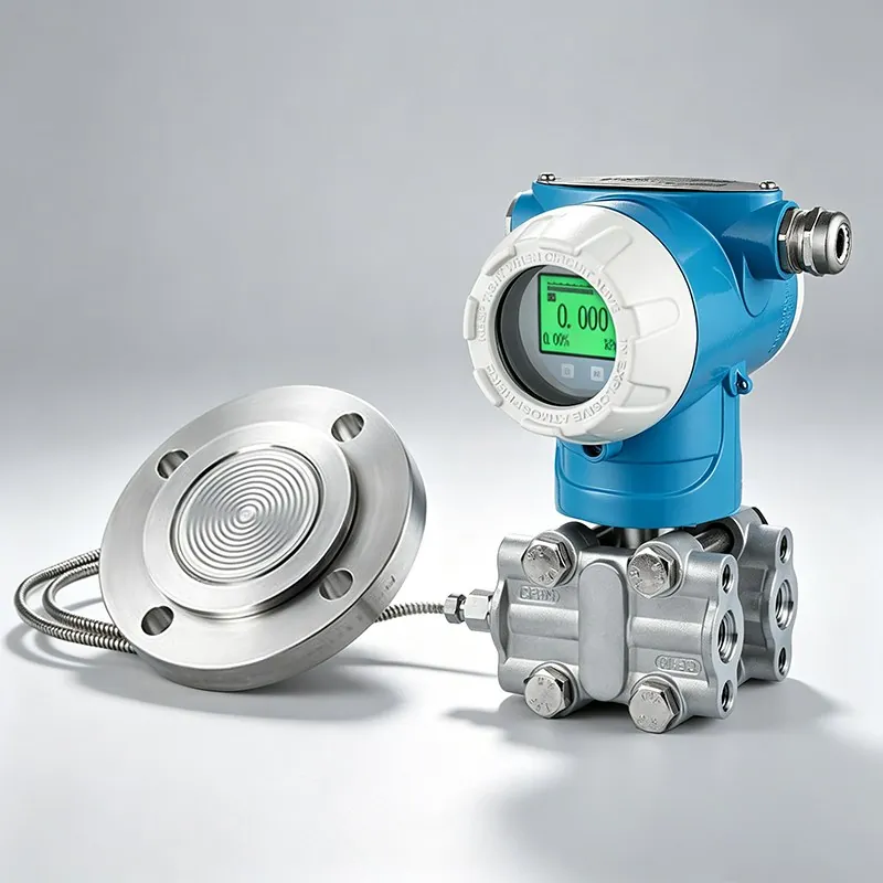
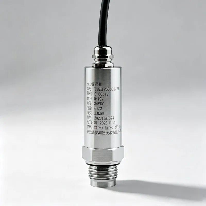
Pressure-transmitter troubleshooting should follow a controlled sequence. Do not open a process connection or enclosure until the responsible site procedure confirms isolation, depressurization, temperature and hazardous-area conditions. The product manual, permit system and qualified personnel take precedence over this general guide.
1. Make the work safe
Identify the complete model and service, review the process medium, isolate the loop where required and confirm that stored pressure or hot fluid cannot be released. For differential-pressure service, understand the manifold and both impulse connections before operating a valve.
2. Separate display, signal and process symptoms
| Observation | First checks |
|---|---|
| No local display and no loop current | Supply, polarity, fuse, cable continuity, terminals and loop load. |
| Local value is plausible but control-room value is wrong | Scaling, units, analogue input range, grounding and signal wiring. |
| Both local and remote values are offset | Process isolation, reference pressure, mounting position and zero procedure. |
| Value is slow or unstable | Impulse blockage/leak, pulsation, trapped gas/liquid, damping and process dynamics. |
| Value saturates at a limit | Actual pressure, configured range, over-range status and sensor limits. |
3. Verify the electrical loop
- Measure supply voltage at the device under operating load.
- Confirm polarity and terminal assignment against the exact manual.
- Check the receiving input, loop resistance, barriers and isolators.
- Compare loop current with the local engineering value and configured lower/upper range.
4. Verify the pressure path
Inspect the process connection, valves, impulse lines, seals and capillaries. Look for blockage, leakage, condensation, trapped gas, frozen fluid, unequal head or heat exposure. A good electronic check cannot correct an incorrect pressure path.
5. Check zero and configuration
Only perform a zero check at a known reference condition. Record the as-found value before adjustment. Confirm pressure reference, units, lower/upper range, damping and output mapping. Do not use zero adjustment to hide a plugged line, elevation error or damaged diaphragm.
6. Escalate with evidence
If the symptom remains, record the model/SKU, serial identity, process conditions, wiring, supply, measured current, displayed value, configuration and test equipment. Contact TYCK with these records. Replace or return the unit when the pressure boundary, sensor or electronics may be damaged; do not improvise a repair in hazardous or safety-related service.