TYCK Product Matrix

Radar Level Transmitters

Compare TYCK radar level transmitters for free-space radar instruments for non-contact level measurement. Review selection factors, applications, limitations, published products and request a configuration-specific quote.

3 Product results

Engineering Selection Guide

Category overview

A free-space radar level transmitter sends a microwave signal toward the product surface and evaluates the returning echo. Frequency is only one design choice; antenna, beam pattern, signal processing, nozzle and target behaviour matter together. Begin with measuring distance and the actual empty and full references, then provide vessel diameter and height, nozzle diameter and length, mounting position, roof shape and every structure that may enter the beam. A narrow beam can help in constrained geometry but does not make obstructions or poor mounting irrelevant.

The target determines available echo margin. Liquids and solids differ, and low dielectric media, turbulent surfaces, steep repose angles, foam, dust or weakly reflecting material can complicate measurement. Vapour and most ordinary gases may have limited effect, but heavy condensation, buildup on the antenna or severe process conditions can still reduce signal quality. Describe filling streams, agitators and surface movement. A supplier should review the proposed antenna and installation against those conditions instead of quoting an unconditional maximum range.

Nozzle and process boundary details are essential. A long narrow nozzle can introduce reflections or restrict the antenna view. The antenna may need to extend beyond a nozzle or use a configuration intended for it, subject to the model drawing. State flange or thread, pressure, temperature, vacuum, corrosion, cleaning and any purge requirement. For solids, include dust, abrasion and impact environment. For hazardous locations, request the exact certificate and installation instructions for the selected housing and electrical connection.

TYCK radar families below provide starting points for liquid and solid applications. An RFQ should include vessel sketch, target medium, dielectric information if known, measuring range, nozzle, obstructions, foam or dust, pressure, temperature, output and required records. Ask for beam guidance, blind-zone information, antenna and wetted materials, process limits and commissioning instructions. Do not transfer range, accuracy or approval statements between 26 GHz, 80 GHz or visually similar variants without a matching document.

Selection factors

Target and surface
State liquid or solid, dielectric information if available, surface agitation, foam, dust, condensation, coating, filling stream and solids repose angle. Describe the least favourable operating state, not only a calm full vessel.
Range and geometry
Give sensor reference, empty and full distances, vessel dimensions, roof and bottom form, nozzle size and length, mounting position and all ladders, coils, agitators or supports near the possible beam.
Antenna and process
Define connection, antenna or lens material constraints, pressure, vacuum, process and ambient temperatures, cleaning, purge and corrosion. Confirm antenna projection and nozzle compatibility from the proposed model drawing.
Signal and commissioning
Specify power, output, communication, display and control-system scaling. Request blind zones, beam information, false-echo setup guidance, parameter record and exact hazardous-area or ingress documentation where required.

Typical applications

  • Chemical, water and utility tanks where non-contact measurement avoids direct probe contact and the beam path can be reviewed.
  • Narrow vessels or small nozzles considered for higher-frequency radar after antenna projection, beam and reflection geometry are confirmed.
  • Silos and granular-solids storage using a suitable antenna and mounting position for dust, surface angle and filling conditions.

Limitations and confirmation points

  • Heavy buildup, condensation, dense foam, dust, weak dielectric reflection and obstructions can reduce echo margin. Frequency alone does not eliminate these application effects.
  • Maximum range and accuracy are conditional on target and installation. Require values tied to the exact antenna, process connection, signal conditions and configured SKU.

Product Catalog

Radar Level Transmitter

3products

Compare Selected 0/4

Select at least two products to compare.

Radar Level Transmitter

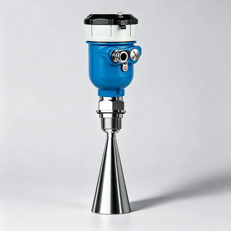
TYCK OCEAN R280 80 GHz Radar Level Transmitter

80 GHz Radar Level Transmitter with configuration-specific range, connection, material and output options

  • Platform modelR280 (double standard transition)
  • Old modelAPT550

Storage and process vessels after medium, geometry and installation position are reviewed.

Documents Request quote
23 SKUs

Radar Level Transmitter

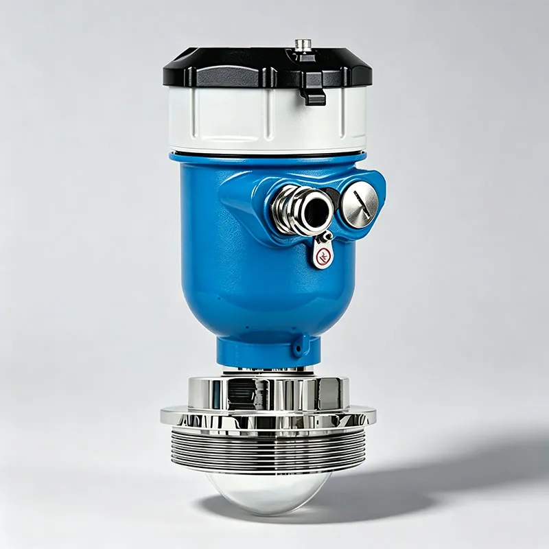
TYCK OCEAN R260 26 GHz Radar Level Transmitter

26 GHz Radar Level Transmitter with configuration-specific range, connection, material and output options

Storage and process vessels after medium, geometry and installation position are reviewed.

Documents Request quote
9 SKUs

Radar Level Transmitter

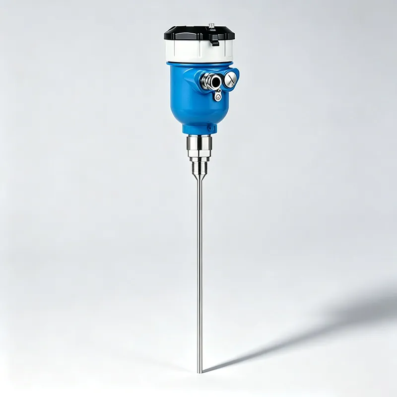
TYCK OCEAN G270 Guided Wave Radar Level Transmitter

Guided Wave Radar Level Transmitter with configuration-specific range, connection, material and output options

  • Platform modelG270 (double standard transition)
  • Old modelAPT155

Storage and process vessels after medium, geometry and installation position are reviewed.

Documents Request quote
4 SKUs

Engineering Selection Guide

Frequently asked questions

Is 80 GHz radar always better than 26 GHz radar?

No. A higher frequency can support a narrower beam or smaller antenna in some designs, while another frequency and antenna may be appropriate for different ranges, buildup, process conditions or existing nozzles. Compare the complete configuration against target dielectric behaviour, geometry, condensation, dust and process limits. The correct choice is supported by the model-specific installation review, not by frequency alone.

Why do nozzle dimensions matter to radar?

The transmitted and returning signal must pass through the nozzle. A long or narrow nozzle can restrict the view, create reflections or place the antenna in an unfavourable position. Provide internal diameter, length, flange or thread and any neck extension. The selected antenna's drawing and installation instructions should show acceptable mounting and whether it needs to project beyond the nozzle.

How should obstacles inside a tank be handled?

First choose a mounting position and beam path that avoid ladders, coils, supports, agitators and filling streams where practical. Mark them on a vessel drawing. Commissioning may include false-echo mapping or masking, but software setup should not be used to excuse a poor physical location. Verify the proposed beam guidance and preserve a commissioning record so later structural or process changes can be assessed.