TYCK Product Matrix

Temperature Transmitters

Compare TYCK temperature transmitters for head-mount and smart temperature transmitters for RTD and thermocouple signals. Review selection factors, applications, limitations, published products and request a configuration-specific quote.

2 Product results

Engineering Selection Guide

Category overview

A temperature transmitter converts a low-level RTD or thermocouple input into a standard signal and may add isolation, linearisation, diagnostics or digital configuration. Start by matching the sensor: RTD type and wiring, thermocouple type and polarity, number of inputs, expected measuring range and fault behaviour. A transmitter configured for one sensor must not be assumed to interpret another correctly. Record the configured input and output range as part of the loop documentation.

The total measurement performance includes the sensor, lead wires, transmitter, ambient temperature and receiving input. Three- or four-wire RTD circuits can reduce lead effects in different ways; thermocouple circuits require compatible extension cable and cold-junction handling. Electrical isolation may help with ground-potential differences, but its presence and rating must be confirmed for the exact model. Reference accuracy at laboratory conditions is only one contributor and should not be presented as the uncertainty of an installed temperature loop.

Installation format affects environment and maintenance. A head-mounted transmitter experiences temperature conducted from the process and surrounding ambient; a rail-mounted device needs a suitable enclosure and wiring route; a field housing adds display and cable-entry considerations. Define supply, load, 4–20 mA or digital communication, sensor-break direction, update time, display and hazardous-area need. If dual inputs, backup or drift diagnostics are important, list the required behaviour instead of assuming every smart transmitter implements it.

The TYCK families below cover head and smart transmitter directions. An RFQ should name the sensor and wiring, configured range and units, output, communication, isolation, housing, ambient conditions and required certificates. Ask for terminal diagrams, input tables and configuration records for the selected code. Commissioning should verify sensor wiring, loop scaling and fault direction at the receiving system. Any diagnostic or protocol function used for maintenance must be supported by the exact manual and firmware information.

Selection factors

Sensor input
Specify RTD or thermocouple type, two-, three- or four-wire circuit, one or two sensors, measuring range, engineering units and required handling of open, shorted or out-of-range input.
Loop performance
Consider sensor tolerance, lead effects, transmitter reference and ambient errors, isolation and input-card performance together. Define the uncertainty objective for the complete measurement loop where one is required.
Output and functions
State supply and load, 4–20 mA, HART or other confirmed interface, damping, fault current direction, display, configuration access and any specific dual-input or diagnostic behaviour.
Mounting and evidence
Define head, rail or field housing, process and ambient heat, vibration, cable entry, enclosure and hazardous-area requirements. Request wiring, configuration, calibration and certificate records tied to the selected SKU.

Typical applications

  • Head-mounted conversion close to an RTD or thermocouple, reducing dependence on a long low-level sensor run when appropriately installed.
  • Rail-mounted interface in panels or skids where terminals, isolation, enclosure temperature and maintenance access are controlled.
  • Field indication and digital configuration where the exact housing, display, protocol and diagnostic functions are confirmed.

Limitations and confirmation points

  • A transmitter cannot correct unknown sensor installation error, poor immersion, an unsuitable thermowell or incorrect extension cable. Loop performance must be assessed end to end.
  • Do not assume dual-input backup, sensor-drift detection, HART variables or hazardous-area approval from the word smart. Verify each function and certificate for the exact order code.

Product Catalog

Temperature Transmitter

2products

Compare Selected 0/4

Select at least two products to compare.

Temperature Transmitter

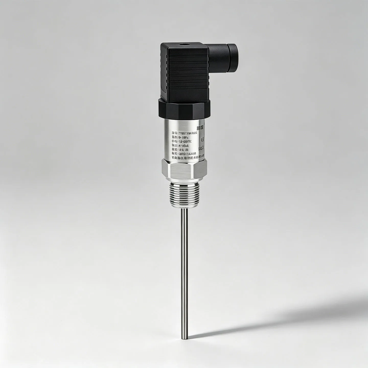
TYCK THERMO T210 Head-Mount Temperature Transmitter

Head-Mount Temperature Transmitter with configuration-specific range, connection, material and output options

  • Platform modelT210
  • Product typeTemperature transmitter

Process skids requiring a standardized RTD or thermocouple signal interface.

Documents Request quote
5 SKUs

Temperature Transmitter

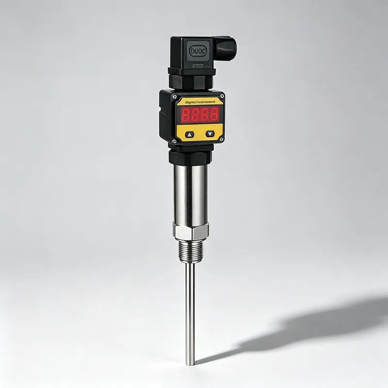
TYCK THERMO T310 Smart Temperature Transmitter

Smart Temperature Transmitter with configuration-specific range, connection, material and output options

  • Platform modelT310
  • Product typeIntelligent temperature transmitter

Process skids requiring a standardized RTD or thermocouple signal interface.

Documents Request quote
25 SKUs

Engineering Selection Guide

Frequently asked questions

Why must RTD wiring be specified?

Two-, three- and four-wire circuits handle lead resistance differently and require compatible sensor and transmitter terminals. The wrong configuration can introduce offset or prevent correct measurement. State the RTD type, number of leads and cable arrangement, then verify the terminal diagram. Commissioning should check continuity and configured input without applying procedures that could damage an intrinsically safe or energised loop.

What does sensor-break behaviour mean?

It defines how the transmitter output responds when it detects an open sensor or another input fault, often by driving the signal toward a configured high or low failure level. The receiving PLC or DCS must recognise that state consistently. Specify the desired direction and any alarm delay, then verify exact current values and supported diagnostics in the selected transmitter manual and loop logic.

Does HART mean the transmitter has the same diagnostics as another model?

No. HART provides a communication framework, while device variables, commands and diagnostic algorithms differ by manufacturer, model and firmware. Identify the functions the asset or control system will use, such as range configuration, sensor status or secondary variables. Confirm the device-description and integration requirements. Do not base maintenance or protective action on a diagnostic that has not been documented and tested.