TYCK Product Matrix

Industrial Level Transmitters

Compare TYCK industrial level transmitters for continuous level transmitters using hydrostatic, capacitance, float or radar principles. Review selection factors, applications, limitations, published products and request a configuration-specific quote.

7 Product results

Engineering Selection Guide

Category overview

A continuous level transmitter turns a changing liquid or solid surface into an analogue or digital value. Principle selection precedes range selection. Hydrostatic instruments infer level from pressure head and liquid density; capacitance devices respond to electrical conditions around a probe; floats follow buoyancy or a magnetic element; radar measures a reflected distance; and guided radar follows a probe path. Each principle reacts differently to foam, vapour, coating, density change, turbulence and vessel internals.

Define the measurement endpoints physically. State vessel reference, empty and full positions, nozzle and mounting elevations, required blind or dead zones and whether the value represents level, interface or volume. If a control system converts level to volume, provide tank geometry and a separate strapping basis. For closed vessels, include vapour pressure and reference arrangement. For hydrostatic measurement, give minimum and maximum density; for electronic echo methods, describe dielectric behaviour and all obstructions near the expected signal path.

Installation and maintenance should be designed together. A submersible transmitter needs cable support, venting strategy and protection from turbulence or sludge. A top-mounted probe needs insertion clearance and consideration of buildup or mechanical loading. A free-space instrument needs a suitable nozzle and aiming path. Side-mounted devices need process isolation and accessible removal. Process pressure, temperature, cleaning chemicals, condensation, washdown and hazardous-area classification influence housing and wetted construction.

The TYCK families on this page represent published continuous-level directions, not interchangeable solutions. Submit medium, density or dielectric information, vessel drawing, measuring span, process envelope, nozzle, internals, output, display, materials and required documents. Ask for an installation drawing and the selected SKU's range, dead zones and process limits. If accuracy or maximum distance is quoted, ensure the statement names the principle, antenna or probe, target and conditions to which it applies.

Selection factors

Principle and medium
Identify liquid, slurry or solid; density and variation; dielectric behaviour where relevant; viscosity, conductivity, foam, vapour, dust, coating and agitation. Use these conditions to compare hydrostatic, float, capacitance and radar options.
Measurement geometry
Provide vessel height and shape, empty and full reference points, nozzle dimensions, mounting elevation, internals, filling stream and access. Separate level, interface, distance and calculated volume requirements.
Process construction
State pressure, vacuum, temperatures, cleaning, corrosion and wetted-material constraints. Define process connection, probe or cable length, submersible cable support, isolation and maintenance removal strategy.
Output and evidence
List power, 4–20 mA or other output, communication, display, alarm use, enclosure and required certificates. Request configuration-specific range, blind zones, drawings and documentation for the proposed SKU.

Typical applications

  • Water and wastewater vessels using hydrostatic, radar or another reviewed principle for continuous control and inventory indication.
  • Chemical tanks where vapour, foam, pressure, material compatibility and nozzle geometry influence the selected transmitter construction.
  • Storage and process vessels integrated with PLC or DCS systems, with level-to-volume calculation kept as a documented separate function.

Limitations and confirmation points

  • Changing liquid density alters hydrostatic inference, while coating and dielectric change can affect contact or echo principles. No technology should be selected without the actual medium behaviour.
  • A maximum measuring distance or headline accuracy is conditional. It must be checked against nozzle, antenna or probe, target, signal quality, dead zones and the specific installed configuration.

Product Catalog

Level Transmitter

7products

Compare Selected 0/4

Select at least two products to compare.

Level Transmitter

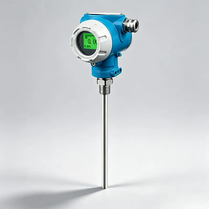
TYCK OCEAN TY822E RF Capacitance Level Transmitter

RF Capacitance Level Transmitter with configuration-specific range, connection, material and output options

  • Measuring range0~5000mm
  • Accuracy±1%FS

Storage and process vessels after medium, geometry and installation position are reviewed.

Documents Request quote
42 SKUs

Level Transmitter

TYCK OCEAN APT910 RF Capacitance Level Transmitter

RF Capacitance Level Transmitter with configuration-specific range, connection, material and output options

  • Current modelAPT910
  • Planning mappingC220 transition candidate for current sale

Storage and process vessels after medium, geometry and installation position are reviewed.

Documents Request quote
43 SKUs

Level Transmitter

TYCK OCEAN APT920 Angled-Probe Capacitance Level Transmitter

Angled-Probe Capacitance Level Transmitter with configuration-specific range, connection, material and output options

  • Current modelAPT920
  • Planning mappingC220 transition candidate for current sale

Storage and process vessels after medium, geometry and installation position are reviewed.

Documents Request quote
6 SKUs

Level Transmitter

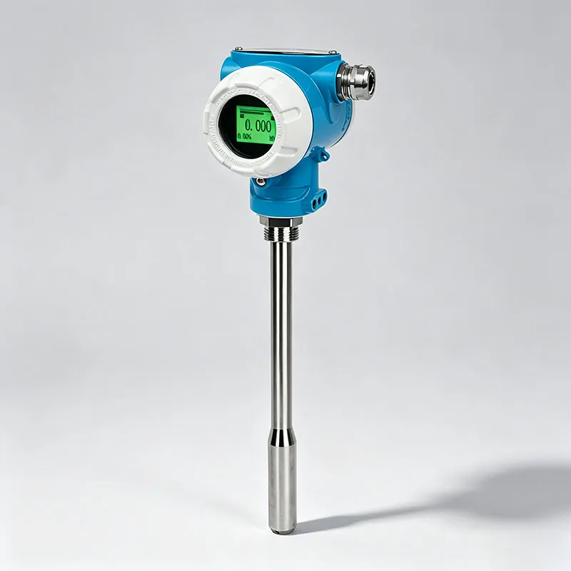
TYCK OCEAN APT980 RF Capacitance Level Transmitter

RF Capacitance Level Transmitter with configuration-specific range, connection, material and output options

  • Current modelAPT980
  • Planning mappingC220 transition candidate for current sale

Storage and process vessels after medium, geometry and installation position are reviewed.

Documents Request quote
35 SKUs

Level Transmitter

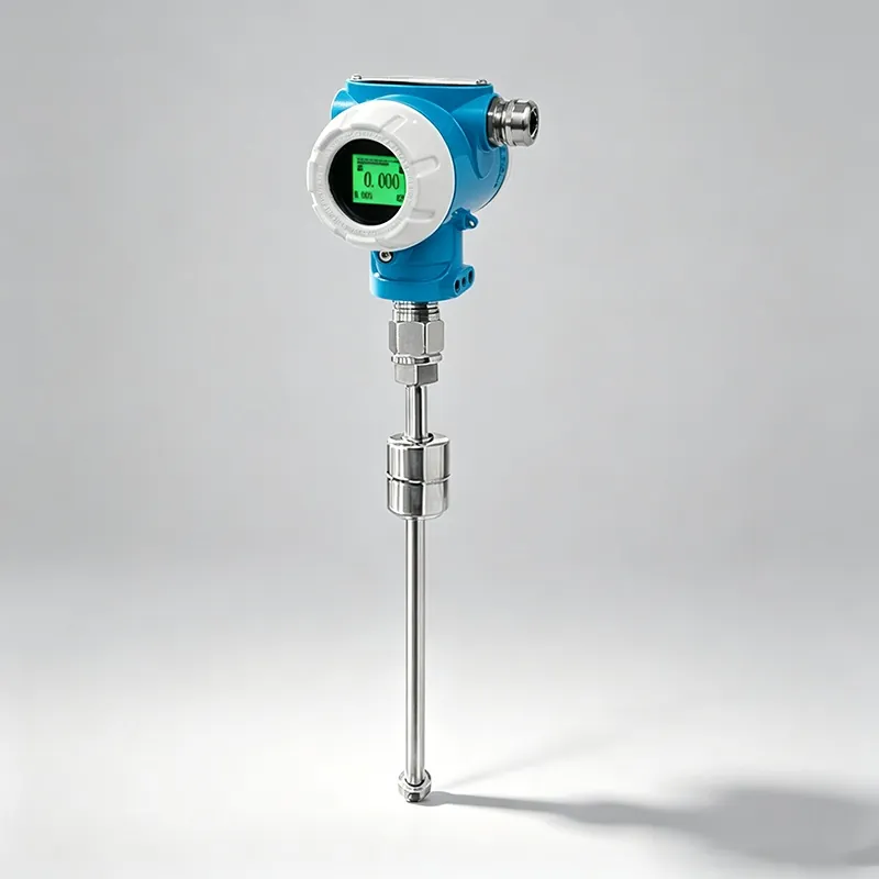
TYCK OCEAN B230 Magnetic Float Level Transmitter

Magnetic Float Level Transmitter with configuration-specific range, connection, material and output options

  • Platform modelB230 (double standard transition)
  • Old modelAPT500

Storage and process vessels after medium, geometry and installation position are reviewed.

Documents Request quote
40 SKUs

Level Transmitter

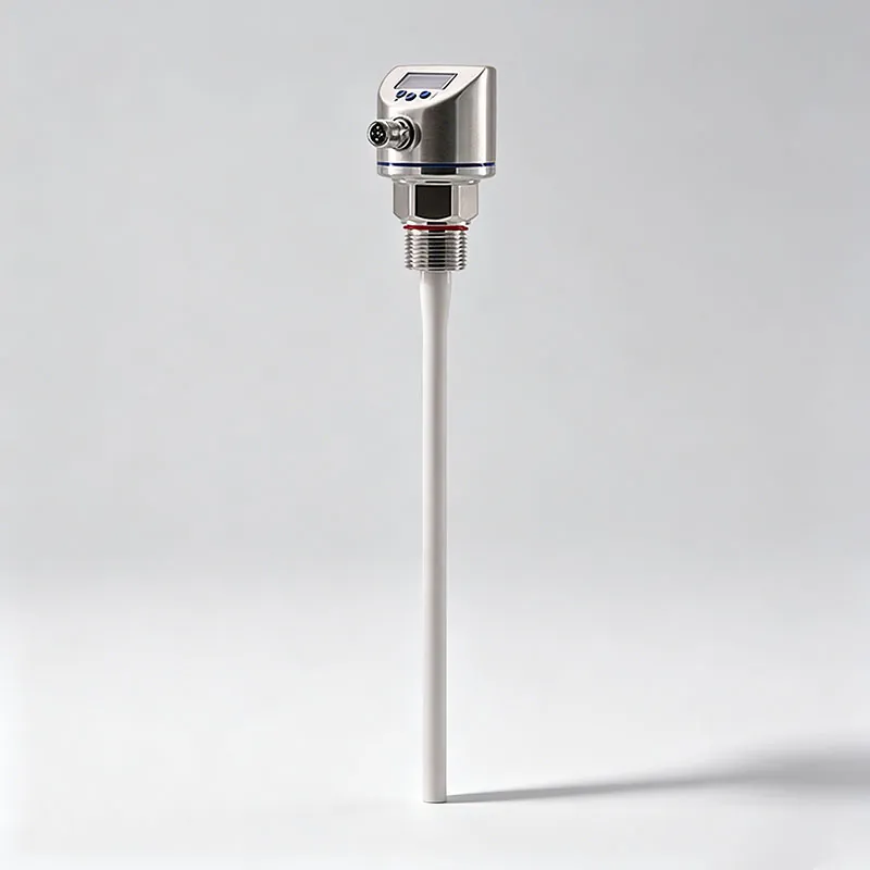
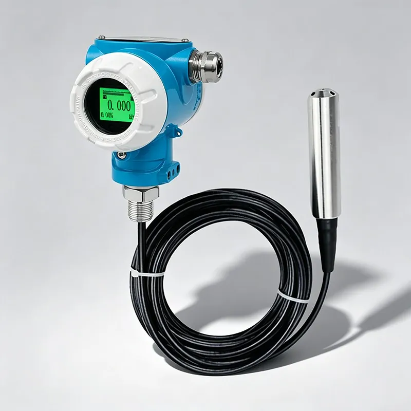
TYCK OCEAN H210 Submersible Hydrostatic Level Transmitter

Submersible Hydrostatic Level Transmitter with configuration-specific range, connection, material and output options

Storage and process vessels after medium, geometry and installation position are reviewed.

Documents Request quote
30 SKUs

Level Transmitter

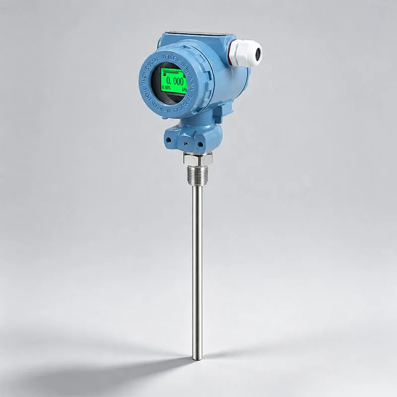
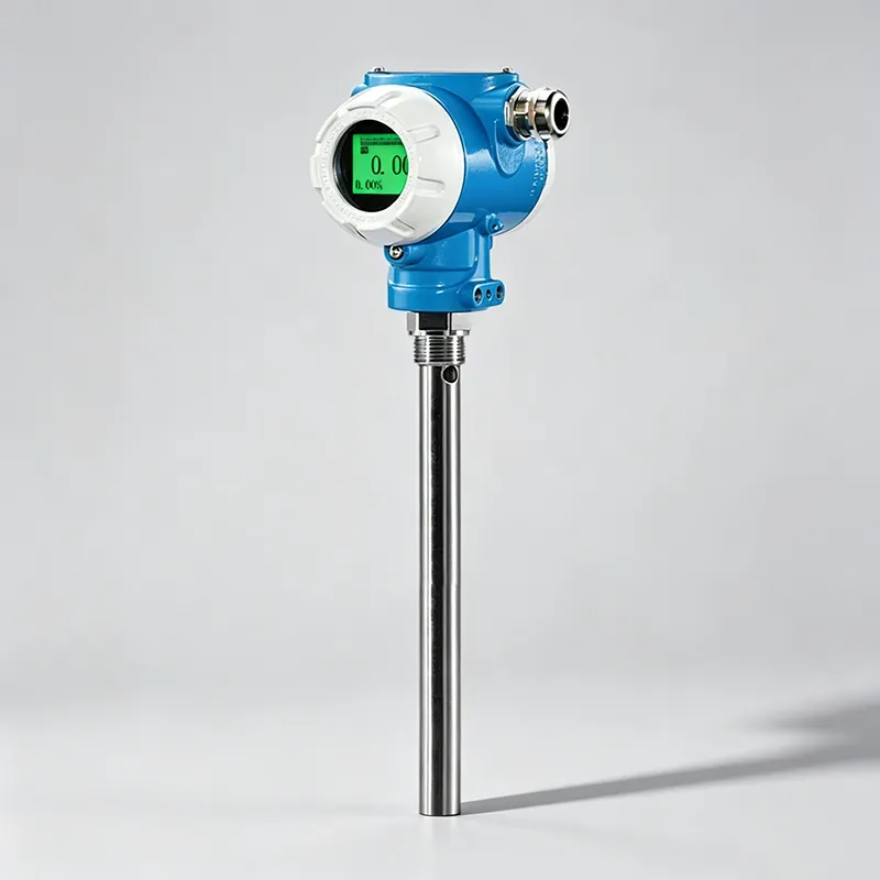
TYCK OCEAN H220 Rod-Type Hydrostatic Level Transmitter

Rod-Type Hydrostatic Level Transmitter with configuration-specific range, connection, material and output options

  • Platform modelH220 (double standard transition)
  • Old modelAPT350

Storage and process vessels after medium, geometry and installation position are reviewed.

Documents Request quote

Engineering Selection Guide

Frequently asked questions

What is the difference between level and volume measurement?

A transmitter usually observes distance, pressure head or another variable related to vertical level. Volume depends on tank shape and may require a strapping table or geometric calculation in the device or control system. State which output is needed and provide approved vessel data. Do not treat a level percentage as a volume percentage unless the vessel geometry and conversion have been deliberately configured and verified.

How does density affect hydrostatic level?

Hydrostatic pressure is related to liquid head and density, so a density change can appear as a level change even when the physical surface is unchanged. Provide density across composition and temperature, not only one nominal value. The engineering design should determine whether compensation, a fixed-density assumption or another measurement principle is suitable. The transmitter itself cannot infer an unknown density change from pressure alone.

Why is a vessel drawing requested for a transmitter?

A drawing reveals nozzle length, mounting elevation, available insertion, internal obstructions, filling streams and the intended empty and full points. Those details affect blind zones, probe length, echo path and process connection. It also prevents range values from being interpreted from different physical references. Mark known foam, sludge or buildup zones and provide maintenance access so the proposed installation can be reviewed before manufacture.